
|
 |
 |
 |
 |
 |
 |
 |
 |
 |
 |
||
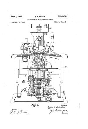
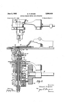
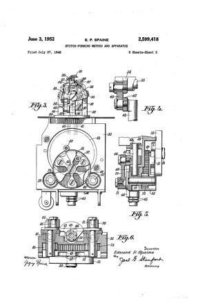
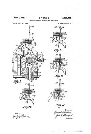
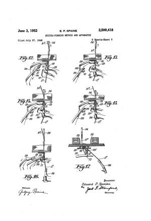
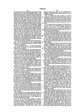
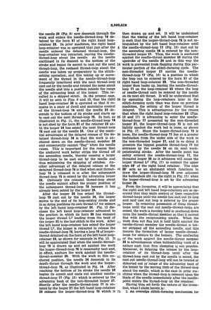
Stitch-forming method and apparatusPatent Number: US 2599418 A June 3, 1952 E. P. SPAINE STITCH-FORMING METHOD AND APPARATUS 5 Sheets-Sheet 1 Filed July 2'7, 1948 glwvewkoz/ Edward P Spaine o'uwzq/ 5 Sheets-Sheet 2 June 3, 1952 E. P. SPAINE STITCH-FORMING METHOD AND APPARATUS Filed July 27, 1948 WWnea a: i m M m 3&1 aw. Din. a 2 5 d Z r a u m H nfl m I m m 0 E m m J v n m w R H P W a w a 5 x mo m w 2. 0 WW. 4 w 55 w 4 E m 5 .4 I 5 My i 2 V O a my a I 2 am t 6am. w 4 @u June 1952 E. P. SPAINE STITCH-FORMING METHOD AND APPARATUS 5 Sheets-Sheet 3 Filed July 27, 1948 w W t M m m Wm m NM, 5 m w W MM mm. 9 5 m 7 l I y 8 M W? June 3, 1952 E. P. SPAINE ,5 STITCH-FORMING METHOD AND APPARATUS I Filed July 27, 1948 v s Sheets-Sheet 4 Edward figvwine June 3, 1952 E. P. SPAINE STITCH-FORMING METHOD AND APPARATUS (I III .r/illigll'ltmi) gn'vwmtov aine/ Edward P W1! Patented June 3, 1952 STITCH-FORMING METHOD AND APPARATUS Edward Paul Spaine, Bridgeport, Conn., assignor 'to'The Singer Manufacturing Company, Elizab'eth. 'N. J a corporation of New Jersey Application July 27, 1 948, Serial No. 40.915 This inventionrelates'to sewing machines and more particularly tochain-stitch'buttonhole sewing machines'o'f the type exemplified by the U. S. reissue patent of E. E. Allen, No. 15,324, reissued April 4, 1922. Theprimary object of the present invention is to provide animproved stich-forming'mechanism capable of forming stitches "in a wide variety of materials, such 'for example as woolens, leather, rubber, etc, 'with'a minimum of requisite adjustment to the mechanism when changing from one to another of said materials. A further object of the present invention is to provide an improved driving mechanism for the lower stitch-forming devices of a'chain-stitch buttonhole machine, which mechanism is quiet and efficient in operation and cheap to manufacture and assemble. Another object of the present invention i to provide a stitch-forming mechanism designed to so handle and control the sewing threads that the usual purl is laid fiat and positioned close to the usual buttonhole slit. A still further object of the present invention is to provide an improved method of forming stitches, which method includes the step of maintaining control of the thread-loop extending from the previous stitch in the work until the next thread-loop cast out by the needle is seized. In sewing the buttonhole, the needle makes its thrusts alternately in the line of the buttonhole slit and through the goods at a distance back from the line of said slit. For convenience, the needle thrusts'through the line of the buttonhole slit will be referred to as the slit" thrusts and those through the goods back from the slit as "depth thrusts. The lower stitch-forming mechanism of the machine disclosed in the above mentioned Allen patent comprises a threaded looper, a non-threaded looper and a right hand and a left hand loop-retainer. During normal stitch-formation in prior buttonhole machines of the type in question, the needle makes its slit thrust in order to project a loop of needle-thread through the goods. As the needle begins its ascent it castsout a needle-thread-loop'which is entered by the advancing threaded looper, carrying with it its own thread which is seized by the left'hand loop-retainer. The left hand loopretainer maintains the looper-thread-loop spread and in position so that the needle on its next penetration, which is its depth-thrust, will pass through the spread "looper-thread-loop. When the needle enters the detained looper-thread-loop, the said loop is releasedby the lefthand loop-re- 5 Claims. (01. 112-65) tainer about the blade of the needle while the needle is descending to the lower end of its stroke. When the needle begins its next upstroke, it casts out a thread-loop which is seized by the advancing non-threaded looper and'carried laterally into position to be seized by the right hand loop-retainer. The right hand loop-retainer maintains control 01 the seized needle-threadloop until the needle on its next slit-thrust penetrates the goods and enters thedetain'ed needlethread-lcop. The right hand loop-retainer releases the detained ne'edle-thread-loop immediately after the needle enters it on its downstroke. In performing the above described stitch-forming cycle, it is essential that the needle on its upstroke cast out a needle-thread-loop of su'fiicient size to insure it seizure by the threaded looper on the slit thrust and then by the nonthreaded looper on the depth-thrust. Failure in the seizure of these needle-thread-loops results in skipped stitches. Normally, there is no serious difliculty experienced in forming suitable needlethread-loops when buttonholing the usual materials. However, when stitching materials such as rubber, leather, woolens, 'etc., which have a tendency to adhere to the blade of the needle and follow it on its upstroke, referred to in the trade as flagging, suitable needle-thread-loops are not always formed by reason of th fact that the material does not properly strip the thread from the needle. Materials of an elastic nature tend to yield up and down with the needle and obviously do not cooperate With the needle in forming satisfactory needle-thread-loops. Considerable thought has been given to the development of work-clamps for eliminating or minimizlng flagging of the work of the vicinity of the reciprocatory needle. While these work-clamps have been more or less successful, it is necessary when shifting from one type of material, such as rubber, to another type, such as leather, to make adjustments to the stitching devices in order to reduce skipping and the like to a minimum. The present invention practically eliminates this heretofore required adjustment of the parts and also makes it possible to use a work-clamp of very simple design. To the attainment of the ends in view, I have provided an improvedlower stitch forming mechanism in which the right and left hand loop-retainers maintain control of their respective thread-loop until after the needle has entered the detained thread-loop, cast out its own threadloop and the needle-thread-loops are seized on the slit-thrust by the threaded looper and on the depth-thrust by the non-threaded looper. The advantages gained by having the loop-retainers hold the thread-loops until the loopers enter the respective thread-loops cast out by the ascending needle are, first, the work is anchored down against the work-supporting surface of the usual needle-throat-member so that it cannot flag during penetration and withdrawal of the needle, second, since the detained thread-loop is not taken up or set until after the advancing looper enters the thread-loop cast out by the needle, the cast out thread-loop is not interfered with by a moving limb of the previously formed threadloop and thereby twisted out of range of the advancing beak of the looper, and; third, the late release of the thread-loops by the retainers allows the needle to clear or move out of these loops before the thread-loops are set thus preventing the thread-loops from snapping oif the needle-point and springing the needle. This is of particular advantage when using heavy threads or the poorer grades of thread. In order to give an understanding of the invention, I have illustrated in the accompanying drawings a selected embodiment thereof which will now be described. In the drawings, Fig. 1 is a front elevational view, partly in section, of a sewing machine embodying the invention. Fig. 2 is an enlarged right side elevational view of a portion of the sewing machine, showing a part of the head, a part of the work-clamp and the lower stitch-forming mechanism with its supporting turret and driving connection in section. Fig. 3 is a rear view of the turret assembly, showing the star-wheel drive and the gearing for operating the loopers and the retainers. Fig. 4 is an enlarged vertical sectional view along the line 4-4, Fig. 2, showing the link connection between the loop-retainer driving bar cross-head and the loop-retainer carrier lever. Fig. 5 is a vertical sectional view taken along the line 5-5, Fig. 1 showing in detail the improved loop-retainer drive. Fig. 6 is a horizontal sectional view taken along the line 66, Fig. 1, showing the parallel arrangement of the two rotary shafts for actuating the loopers and the retainers. Fig. '7 is a right side elevational view of the turret with the needle-throat member and a part of the turret in section, showing the stitch-forming mechanism componentsv and sewing threads in position at the commencement of a stitchforming cycle; the needle beginning its slit-stitch descent and the previous needle-thread-loop held by the right hand loop-retainer. Fig. 8 is a right side elevation of the stitchforming devices with the needle-throat member in section, showing the first step in the stitchforming cycle in which the needle has descended to begin the slit-stitch and entered the spread loop of needle-thread detained by the right hand loop-retainer. Fig. 9 illustrates the stitch-forming devices in the next position of stitch-formation in which the needle is at the lower end of its stroke and the previous needle-thread-loop is still detained by the right hand loop-retainer. Fig. 10 shows the next position of stitchformation in which the threaded looper has advanced and entered the next needle-thread-loop cast out by the ascending needle, the previous needle-thread-loop still detained by the right hand loop-retainer, whereby the work is an- 4. chored against the top of the needle-throat member and prevented from flagging with the ascending needle. Fig. 11 shows the next position of stitchformation in which the thread-carrying looper is traveling toward the end of its needle-threadloop seizing stroke, the right hand loop-retainer moving backward to release the previous needlethread-loop so that it can be properly set in the work. Fig. 12 shows the next position of stitch-formation in which the thread-carrying looper has traveled to the end of its needle-thread-loop seizing stroke and in so doing has positioned a limb of its own thread for seizure by the advancing left hand loop-retainer. Fig. 13 shows the position of the stitch-forming devices substantially at the completion of the slit-stitch, in which position the looper-threadloop is detained on the left hand loop-retainer. Fig. 14 shows the next position of stitch-formation in which the needle has penetrated the work to form the depth-stitch and has entered the looper-thread-loop held spread by the left hand loop-retainer. Fig. 15 shows the needle on its upstroke, having traveled sufficiently far to cast out a needlethread-loop which is entered by the nose of the non -threaded looper, the looper-thread-loop being still detained by the left hand loop-retainer in a manner to anchor the work against the top of the usual needle-throat member. Fig. 16 illustrates the parts in the position after the non-threaded looper has seized the needlethread-loop cast out by the needle and presented said seized loop for engagement by the advancing right hand loop-retainer. Fig. 17 represents a transverse vertical sectional view, with the loopers in elevation, of the parts shown in Fig. 16, illustrating the right hand loop-retainer engaging the work-limb of the needle-thread-loop presented by the non-threaded looper. Referring in detail to the accompanying drawings, the invention is shown as embodied in a buttonhole machine having, in general, construetive features which are substantially in accordance with the disclosure in the above mentioned Allen Reissued Patent No. 15,324. The machine is constructed with a frame having a bed 20 and an overhanging head 2|. Supported on the bed 20 is the usual traveling work-holder comprising the lower work-supporting plates 22 and the upper clamping members 23, to which work-holder longitudinal feed and sidewise shifting movements are imparted for spacing the stitches of a buttonhole. The work-holder is moved relative to the stitch-forming mechanism during the sewing period as well as prior and subsequent to the sewing period by the usual connections, as disclosed in said Allen Reissued Patent No. 15,324. The stitch-forming mechanism comprises the usual upper endwise reciprocatory and laterally vibratory needle 24 which cooperates with the under stitch-forming devices carried by a rotary turret 25; such under devices including the usual threaded and non-threaded loopers 26 and 27, respectively, and the right and left hand loopretainers 28 and 29. The turret 25 carries the usual needle-throat member 30 provided with a needle-receiving aperture 3|. The stitch-forming mechanism is driven by means including a main sewing shaft 32 journaled in the bed 28. The main sewing shaft 32 is connected by suitable means (not shown) to the endwise reciprocatory and laterally vibratory needle 24. Rotation of the main sewing shaft will effect operation of the upper and lower stitch-forming devices in a manner to produce two-thread chainstitches. It is equally common to provide the lower stitch-forming mechanism with two nonthreaded loopers, instead of with one threaded looper and one non-threaded looper, in which case the resulting seam will be a single thread chain-stitch concatenation. Also, it is common to use two threaded'loopers, in which case the resultant seam is a three-thread arrangement. The advantages attained by the use of the present in vention are present whether the machine is fitted to sew with one thread, two threads or'three threads. The rotary turret 25 carrying the lower stitchforming devices is formed with a tubular shank 33 (Fig. 2) journaled in a vertical bearing bushing 34 pressed into a frame-block 35 detachably secured to the machine-bed 2E3. Extending upwardly from the turret 25 is a post 36 into the upper extremity of which is threaded a horizontal pivot-screw 3? on which is fulcrumed a looper-carrier 33 (Fig. 3) formed with oppositely extending arms to which are rigidly secured the threaded and non-threaded loopers 26 and 21. The actuating connections for the loopers 26 and 27 comprise a link 39 (Figs. 3 and 4) secured at its upper end to one arm of the looper-carrier 38 and at its lower end to the offset head 40 formed on the upper end of a tubular rod M fitted to slide within the tubular shank 33 of the turret 25. At its lower end the tubular rod has threaded thereon the spaced collars 52 (Fig. 1) between which is disposed the apertured extremity of an arm 53 clamped on a guide-rod 44 journaled to slide vertically in bearing lugs provided on the frame-block 35. The arm 43 is thus adapted to lift and lower the tubular rod 4| and thereby rock the looper-carrier 38 about its fulcrum-stud 3?. The means for raising and lowering the arm as preferably includes a link 55 (Figs. 1 and 6) connected at its lower end to a crank 55 carried on the forward end of a short rotary shaft 41 journaled in the frame-block 35. At its inner end, the shaft t1 carries a pinion 48 meshing with a gear 49 of triple its size supported by a stud 59 (Fig. 2) carried by the frameblock 35. Secured to the rear face of the gear 49 is a star-wheel 5! which has imparted to it stepby-step turning movements by means of a pair of riving pins 52 arranged diametrically of a driving disk 53 secured to the main sewing shaft 32. As fully explained in the U. S. patent of Allen et al. No. 1,372,473, dated March 22, 1921, the teeth of the star-wheel 51 are shaped such wise as to produce periods of appreciable dwell between the periods of motion of the star-wheel. During these periods of dwell the crank 46 is held stationary at one or the other of its positions midway between its extreme up and down positions, thus arresting the motion of the loopers to avoid interference with the loop-retainers now to be described. Cooperating with the threaded looper 25 is the loop-retainer 28 hereinafter referred to as the right hand loop-retainer. As shown in Figs. 2 and '7, the right hand loop-retainer 28 is mounted on a carrier-lever 54 fulcrumed to oscillate about a horizontal pin 55 supported at its opposite ends by the spaced vertical posts 56 extending upwardly from the turret 25. At its free end the right hand loop-retainer 28 is formed with a curved and pointed.loop seizing'horn 51 which, as will be explained later, functions to enter and retain control of a needle-thread-loop presented to the loop-retainer by the non-threaded looper 21. Adjacent the right hand loop-retainer 28 is a second or left hand loop-retainer 29 .(Fig. 2) mounted on a carrier-lever 58 also fulcrumed on the horizontal pin 55. Like the first loop-retainer 28, the second loop-retainer 29 is formed at its free end with a curved and pointed loop-seizing horn 59 (Fig. 12). The two loop-retainers 28 and 29 are oscillated on their common fulcrumpin by means including two links 50 and GI (Fig. '2) connected at their upper ends to the carrier-levers 54 and 58 and at their lower ends to the opposite ends of a cross-head 62. The cross-head '62 is preferably integral with the upper end of an actuating rod 63 bored longitudinally to provide a looper-thread passageway 64. The rod 63 is'slidingly fitted within the tubular rod 4| for 'endwise reciprocation. The improved means for reciprocating the loop-retainer actuating rod 63 is substantially like that employed for operating the loopers 26 and 27. It will be seen in Figs. 1, 5 and 6 that the actuating rod 63 .has threaded thereon spaced collars 65 between which is located the lower end of an arm 66 having its upper end clamped upon a guide-rod 61 journaled to slide vertically in bearing bushings 68 and 69 (Fig. 5) provided in the frame-block 35. The means employed for raising and lowering the arm 56 preferably includes a link 70 connected at its lower end to a crank H carried on the forward end of a second rotary shaft 12 journaled in the frame-block 35 in substantial parallelism with the shaft 41. At its inner end, the shaft 12 carries a pinion i3 meshing with the gear 49; the ratio between the gear and pinion being one-to-three. It will be understood that intermittent rotation of the gear 49 will impart an interrupted motion to the loopretainer actuating rod 63 and that the motion derived from the star-wheel BI is modified by the crank H passing through dead-center at the opposite-ends of its stroke. The resultant actuation of the two loop-retainers 28 and 29 when properly timed with the actuations of the loopers 26 and 21 effects a mutual cooperation between the loopers and loop-retainers resulting in improved stitch-formation. Figs. 7 to 16, inclusive, are explanatory of the various steps in stitch-formation and attention is directed thereto for an understanding of the advantages gained by using my improvement. Let it be understood that in the present case a complete stitch-forming cycle includes two complete reciprocations of the needle, the cycle beginning with the needle in raised position preparatory to descending to form the slit-stitch. Since two reciprocations of the needle are included in the complete stitch-forming cycle, the arm-shaft of the machine rotates through 720 degrees. With this in mind, assume now that the machine has produced several stitches and that the parts are in the position shown in Fig. 7, with a loop 14 of needle thread N detained and held spread on the horn 51 of the right hand loop-retainer 28, and with the thread-carrying looper 26 in a position of dwell awaiting the descent of the needle 24 to begin the slit-stitch. It will be understood that the needle-threadloop .14 extends from the previous stitch in the work and that :it is sufiiciently taut as to pull the work down and anchor it upon the needlethroat member 30. Continuing with the cycle, the'needle 24 (Fig. 8) now descends through the work and enters the needle-threadloop 14 detained by the horn 51 of the right hand loopretainer 28. In prior machines, the right hand loop-retainer was so operated that just after the needle entered the detained thread-loop, the loop-retainer was retracted, leaving the needlethread-loop about the needle. As the needle continued in its descent to the bottom of the stroke and began its ascent to cast out the next thread-loop, the reelased thread-loop about the needle was taken up preparatory to the stitchsetting operation, and this taking up or movement of the thread in the needle-thread-loop frequently interfered with the next thread-loop cast out by the needle and twisted the same about the needle and into a position outside the range of the advancing beak of the looper. This resulted in a skipped stitch. In the present case, it will be seen in Figs. 9 and 10, that the right hand loop-retainer 28 is operated so that it remains in a state of dwell and maintains control of the thread-loop 14 until the needle 24 descends to the bottom of its stroke and starts up to cast out the next thread-loop 15. In fact, as illustrated in Fig. 11, the needle-thread-loop 14 is not shed by the horn 51 of the retainer 28 until the looper 26 has seized the next thread-loop 15 cast out by the needle 24. One of the essential advantages of the delayed release of the detained thread-loop 14 is that the work is anchored down on the needle-throat member 30 and consequently cannot flag when the needle raises. This is important for the reason that the anchored work better strips the thread off the ascending needle, thereby causing a larger thread-loop to be cast out by the needle and thus minimizing the skipping of stitches. Another advantage of the delayed release of the detained thread-loop 14 is that when said threadloop 14 is released it is after the subsequent thread-loop 15 is seized by the advancing looper 26. Obviously the released thread-loop about the needle cannot affect the proper position of the subsequent thread-loop 15 because it has already been seized by the looper 26. After the looper 25 has seized the threadloop 15 cast out by the needle 24, the looper moves to the end of its loop-seizing stroke and in so doing positions its own thread L for seizure by the left hand loop-retainer 29. Fig. 12 discloses the left hand loop-retainer advanced to the position in which its horn 59 has engaged the looper thread L leading from the beak of the looper 25 to the last stitch in the work. After the left hand loop-retainer has seized the looper thread L the looper is retracted to release the needle-thread-loop 15, leaving a loop 16 of looperthread detained on the horn of the left hand loopretainer 29, as shown for example in Fig. 13. It will be appreciated that when the needle-threadloop 15 is drawn up and set against the work the looper-thread-loop 16 is reasonably taut and, in effect, anchors the work against the needlethroat-member 30. With the work in this anchored position, the needle 24 descends in its depth-thrust through the work and the looperthread-loop 16, as illustrated in Fig. I4. After reaching the bottom of its stroke the needle 24 begins its ascent and casts out another needlethread-loop 11 (Fig. 15) which is'entered by the advancing beak of the non-threaded looper 21. Shortly after the needle-thread-loop 11 is entered by the looper 21 the left hand loop-retainer 29 releases the looner-thread-loop 16 which is 8 then drawn up and set. It will be understood that the timing of the left hand loop-retainer is such that the looper-thread-loop 16 is not relinquished by the left hand loop-retainer until the needle-thread-loop 11 (Fig. 15) cast out by the ascending needle 24 is entered by the nonthreaded looper 21. Thus, the work is anchored against the needle-throat member 30 during the upstroke of the needle 24 and in this way the work is prevented from flagging during this particular portion of the stitch-forming cycle. The non-threaded looper 21 carries the needlethread-loop 11 (Fig. 16) to a position in which the loop can be entered by the horn 51 of the right hand loop-retainer 28. The non-threaded looper then backs up, leaving the needle-threadloop 11 on the loop-retainer 28 where the loop of needle-thread cain be entered by the needle on its next slit thrust. It will be understood that by operating the loop-retainers later in the stitch-forming cycle than was done on previous machines, the setting of the looper thread is delayed. This is advantageous for the reason that when the right hand loop-retainer 28 (Figs. 16 and 17) is advancing to enter the needlethread-loop 11 presented by the non-threaded looper 21, the looper-thread-loop 15 is not set tightly against the work but is loose, as shown in Fig. 17. Since the looper-thread-loop 15 is loose, the needle-thread-loop 11 lies at a greater inclination from the under side of the work to the non-threaded looper 21, and in so doing it presents the biggest possible thread-loop 11 for entrance by the needle 24 on its next workpenetrating stroke. After the needle point has safely entered the needle-thread-loop 11, the threaded looper 26 as it advances will cause the looper thread L (Fig. 17) to contact the upper edge 28' of the right hand retainer. The edge 28 acts as an abutment which functions to draw the looper-thread-loop 16 over adjacent the buttonhole slit (to the right in Fig. 17) when the looper-thread-loop is set by the advancing looper 26. From the foregoing, it will be appreciated that the right and left hand loop-retainers are so 0perated that they main control of their respective thread-loops until the needle has cast out its loop and said cast out loop is entered by the proper looper. In retaining possession of these threadloops until the cast out needle-thread-loops are seized, the work is forcibly held or anchored down upon the needle-throat member so that it cannot flag with the reciprocating needle. When the work does not flag but is held tight against the needle-throat member the needle-thread is better stripped off the ascending needle, and this insures the formation of larger needle-threadloops for seizure by the loopers. The anchoring 0f the work against the needle-throat member 30 is advantageous when buttonholing work of a nature such that firm clamping i not possible. Moreover, in delaying the release by the loopretamer of its thread-loop until after the thread-loop cast out by the needle is seized, the cast out needle-thread-loop will not be twisted or distorted out of range of the advancing beak of the looper by the moving limb of the thread-loop about the needle, which is the case in prior machines when the thread-loop is released upon the blade of the needle immediately after the needlepoint enters the thread-loop on the retainer. Having thus set forth the nature of the invention, what I claim herein is: 1. An overedge stitch-forming mechanism for sewing machines, comprising, upper-thread mechanism having an endwise reciprocatory and laterally vibratory thread-carrying needle, and under thread-handling mechanism including a pair of loopers adapted alternately to enter thread-loops presented by said needle, a pair of loop-retainers each adapted for seizing a threadloop from its respective looper, actuating mechanism for operating each of said loop-retainers causing it to seize a thread-loop from its respectiv looper and present it for entrance by said needle, and loop-retainer dwell producing connections in said actuating mechanism for causing each of said loop-retainers to delay the release of the thread-loop seized thereby until one of said loopers enters the thread-loop cast out by the needle on its next ascent. 2. The herein described method of forming a seam, which consists in passing a thread-carrying needle through the work and causing it to cast out a needle-thread-loop, seizing said needlethread-loop and passing a first looper threadloop through said needle-thread-loop, seizing said first looper-thread-loop and holding it in a position to be entered by the needle on it next workpenetrating stroke, passing the needle through said first looper-thread-loop and causing said needle to cast out another needle-thread-loop, seizing said last formed needle-thread-loop and then releasing said first looper-thread-loop. 3. An overedge stitch-forming mechanism for sewing machines, comprising, upper-thread mechanism having an endwise reciprocatory and laterally vibratory needle, and under threadhandling mechanism including a pair of loopers adapted alternately to enter thread-loops presented by said needle, loop-retainers for seizing thread-loops from said loopers and presenting them for entrance by said needle, and driving means for actuating said loopers and loop-retainers including a main shaft, a looper actuating shaft and a loop-retainer actuating shaft each operatively connected independently of the other 4. An overedge stitch-forming mechanism for sewing machines, comprising, upper-thread mechanism having an endwise reciprocatory and laterally vibratory needle, and under threadhandling mechanism including a pair of loopers adapted alternately to enter thread-loops presented by said needle, loop-retainers for seizing thread-loops from said loopers and presenting them for entrance by said needle, and drivin means for actuating said loopers and loop-retainers including a main shaft, a looper actuating shaft and a separate loop-retainer actuating shaft, means for operatively connecting each of said actuating shafts to its respective threadhandling implement, and a common dwell-pro- 'ducing connection between said main shaft and said actuating shafts for imparting a variable motion to said actuating shafts. 5. An overedge stitch-forming mechanism for sewing machines, comprising, upper-thread mechanism having an endwise reciprocatory and laterally vibratory needle, and under threadhandling mechanism including a pair of loopers adapted alternately to enter thread-loops presented by said needle, loop-retainers for seizing thread-loops from said loopers and presenting them for entrance by said needle, and driving means for actuating said loopers and loop-retainers including a main shaft, driving connections for operating said loopers and loop-retainers including a pair of rotary shafts, a gear, a pinion secured on each of said rotary shafts and meshing with said gear, and a star-wheel connection between said gear and said main shaft for imparting variable rotary motions to said rotary shafts. EDWARD PAUL SPAINE. REFERENCES CITED The following references are of record in the file of this patent: UNITED STATES PATENTS |
|||
or send email to 
(sorry, the email addresses
that used to be here have
been disabled due to spam
attacks.)
|